Failure…Failure…Failure…
 |
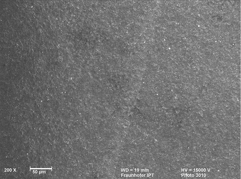 |
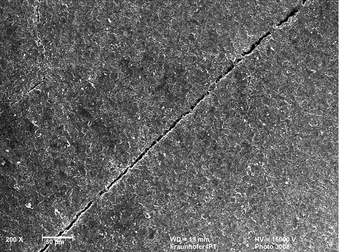
| Pict. 1 (electr. micr. photo) – crack easy to detect with a „new“ PCD blank | Pict. 2 (electr. micr. photo) – crack to detect under magnification with a „new“ blank |
 |
 |
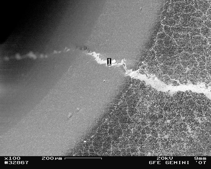
| Pict. 3 (electr. micr. photo) – crack after sintering, sintering material fills the gap in the PCD |
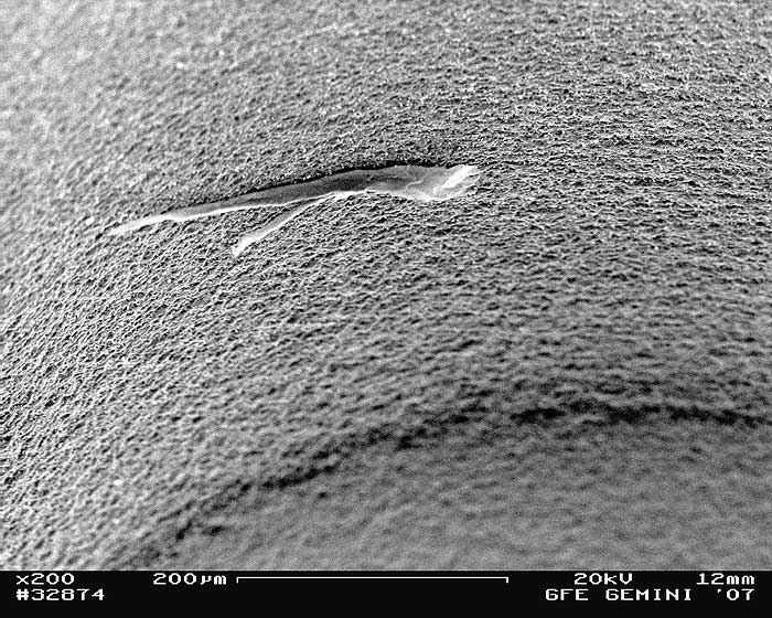
Pict. 4 (electr. micr. photo) – Detected while ultrasonic treatment: cavity in the structure |
 |
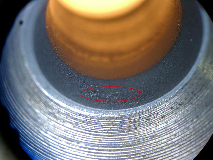 |
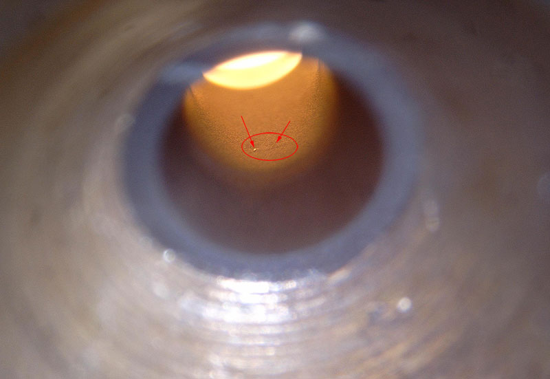
| Pict. 5 (light-optical microscope) Detected during ultrasonic shaping: punctual defect in the pcd structure and crack in the drawing cone | Pict. 6 (light-optical microscope) Similar pict. 5 Crack in the entrance area |
Since the beginning the wire die manufacturers could detect faulty material with the PCD.
These defects occur during the process of manufacturing (laser drilling, ultrasonic shaping and polishing).
But also while using the PCD tools in the drawing process (breakage of the wire, defect of the die or both).
Defects shown in the pictures on the right are all found in pcd products of well-known manufacturers.